Multi-Subnet Servers
Articles » Redundant Layer-3-Only Data Center Fabrics » Multi-Subnet Servers
Networking configuration on servers offering the same services on IP addresses belonging to multiple subnets (see previous page for details) is no different from traditional networking configuration:
- The server has multiple interfaces;
- IP addresses and subnet masks are configured on all interfaces using static configuration or DHCP/DHCPv6;
- Default routes are configured on all interfaces to ensure redundancy;
- IP forwarding should be disabled on the server, in particular when you’re running routing protocols on it instead of using static- or DHCP-derived default routes.
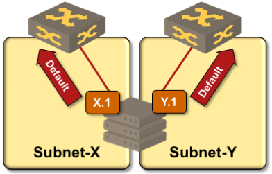
Server setup with multiple independent IP interfaces
Assuming an application client figures out how to connect to one or more of the available server IP addresses1, TCP-based applications require no changes in the server-side application code – TCP stack ensures that the return packets are always sent from the same IP address to which the incoming packet was sent.
TCP/IP stack does not keep session state for UDP applications; the application itself must ensure that UDP responses are sent from the same address to which the UDP requests were sent. This behavior is already implemented in well-written UDP applications like DNS servers.
While “use multiple IP addresses on a server” setup looks exceedingly simple, it’s rarely used due to numerous real-life challenges including:
- Client-side support. The client must be able to connect to one of many potential destination IP addresses, and quickly fail over to an alternate IP address when the current one becomes unavailable (for example, due to server uplink failure). See previous page for details;
- Symmetrical traffic flow. Responses to traffic received on an interface should be sent from that same interface, in particular in environment with air-gapped subnets like SAN-A/SAN-B storage networks (see the following diagram).
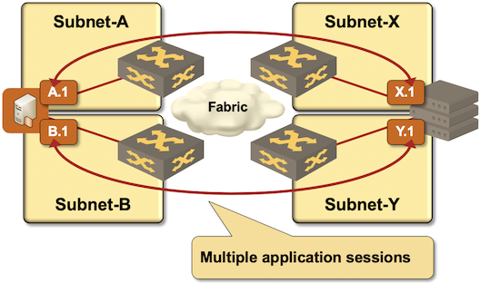
Symmetrical traffic flow in air-gapped SAN-A/SAN-B networks
You could achieve symmetrical traffic flow with policy-based routing selecting outgoing interface based on source (local) IP address, but even this solution requires extensive configuration of the server TCP/IP stack. You might be tempted to use one VRF per server uplink (similar to IPsec/DMVPN front-door interfaces), resulting in an even more complex setup. Most real-life solutions (including common iSCSI designs) therefore use one of these kludges:
- Clients and servers residing in a single IP subnet, usually requiring stretched VLANs or mismatched IP subnet masks in combination with proxy ARP;
- Static routes for remote subnets configured on a single uplink. See next page for details.
-
Applications stacks using load balancers in front of a group of servers could leverage load balancer functionality to implement multi-subnet servers even for applications that cannot deal with this multiple server IP addresses by hiding server IP addresses behind a virtual IP address of a load balancing pool. ↩︎
More Information
If you’re building a cloud infrastructure, explore the webinars from the Cloud Infrastructure and Software-Defined Data Centers series, in particular the Designing Cloud Infrastructure and Designing Active-Active and Disaster Recovery Data Centers.
If you’re building a data center fabric, start with the Leaf-and-Spine Fabric Architectures and Designs webinar and use the information from Data Center Fabric Architectures webinar when selecting vendors and equipment.
You get all the above webinars with the ipSpace.net subscription.