Queuing Principles
Technology Resources » QoS Mechanisms » Queuing Principles
An interface output queue can form only if the arrival rate of packets (routed or router-generated) is higher than the departure rate (usually the interface line speed). If the arrival rate is lower than the departure rate, the packets are sent immediately and no queuing is performed even when it’s configured on an interface.
An interface input queue can form on software switching platforms when the packet arrival rate exceeds the forwarding capacity of the CPU.
Virtual interfaces (VLAN interfaces, subinterfaces, tunnels…) have no concept of departure rate (there is no hardware directly tied to them) and thus cannot perform output queuing. It’s impossible to configure a queuing service policy (or any other queuing mechanism) directly on a virtual interface.
Where to Queue
Every interface in a modern network device using software packet switching contains Direct Memory Access (DMA) subsystem that supports hardware-implemented FIFO receive and transmit queues. This mechanism streamlines the transmission process and minimizes the load on the main CPU. The main CPU (after routing the packet, performing output checks and prepending a layer-2 header) inserts the packet into the FIFO output queue where the interface picks it up when it’s ready to transmit another packet. The interface only interrupts the CPU when it needs more packets to transmit (some lower-speed interfaces interrupt the CPU on every successfully transmitted packet).
The hardware queue shared between the CPU and the interface chipset cannot be reordered, as the CPU has no control over the operation of the interface hardware that might pick up a packet at any time. Once a packet enters the hardware queue, its position in the queue cannot be changed.
The various queuing mechanisms offered by Cisco IOS are implemented in software queues beyond the hardware queue. If the hardware queue is full at the time a packet is routed to an interface, the packet is entered into one of the software queues; otherwise it’s appended at the end of the hardware FIFO queue. The CPU transfers the packets from the software queues to the hardware queue when the interface interrupts it asking for more output packets. Based on the hardware queue size, more than one packet can be transferred from the software queues into the hardware queue on each interrupt.
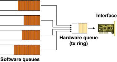
Software and hardware queues
The hardware queue size is computed automatically by Cisco IOS; the queue size depends on the interface hardware, its line speed and the router model (CPU speed). The router tries to minimize the hardware queue size (to minimize the FIFO part of the queuing model) while ensuring that the increased interrupt rate will not overwhelm the main CPU. Usually, the hardware queue has only one or two entries on low-speed (< 2 Mbps) links and can be as long as 128 entries on high-speed (> 100 Mbps) interfaces (more details).
The size of the hardware queue can be configured with the tx-ring-limit interface configuration command and inspected with the show controllers interface command (look for the tx_limit field or the TX ring size). This setting should be changed only if the long hardware queue size causes unacceptable jitter or delay on QoS-sensitive applications) (for example, VoIP traffic).
If no fancy queuing is configured on the interface, FIFO queuing is used on the interface and the packets sent to the interface are enqueued directly into the hardware transmit ring (more details). The size of the FIFO output queue is controlled with the hold-queue out interface configuration command.
Implementation Details
The FIFO queue shared between the main CPU and the interface hardware is almost always implemented with a structure of transmit buffer descriptors. To minimize the hardware complexity, the descriptors are logically organized in a tx-ring (actually it’s a wrap-around array) and the FIFO queue is implemented as a moving set of buffer descriptors.
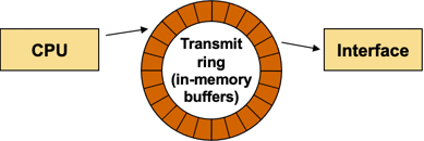
Transmit ring between CPU and output interface
The main CPU inserts a packet in the FIFO queue by:
- writing the packet’s buffer address into the next free TX descriptor;
- setting a bit in the descriptor indicating that it now belongs to the interface hardware;
- incrementing the free descriptor pointer (and wrapping it around at the end of the descriptor array).
When the interface transmits a packet, it also polls the next descriptor to figure out if there’s another packet to be transmitted. If the next TX descriptor indicates a packet is available, the transmission process continues with the next packet, otherwise the transmission circuitry enters the idle state.
In the idle state, the interface hardware periodically polls the next descriptor and starts the transmission as soon as it finds a descriptor marked as belonging to the interface. The periodic polling can introduce additional latency beyond the serialization delay.
Example: The default polling interval for the AMD PCnet PCI Ethernet controllers used in some low-end routers is approximately 2 msec. The transmission delay of a lightly loaded (Fast)Ethernet interface can thus exceed the transmission delay of a more utilized interface. The polling delay on serial interfaces is usually lower; for example, Serial Communication Controllers in the MPC8272 processor used by the 870-series routers or the MPC860 processor used by the 2600-series routers poll the TX descriptors every 8-32 TX clocks.
Software-Only Queuing
As explained in the When to Queue section, software-only interfaces don’t support queuing mechanisms as their packet departure rate is undefined (packets sent to a software interface are always transferred immediately to a hardware interface). If you want to implement queuing on a software interface, you have to introduce artificial backpressure in form of traffic shaping.
Traffic shaping always introduces additional latency and jitter. Furthermore, it imposes a hard limit on packet departure rate; even if the underlying physical interface is not busy, the shaped traffic will be rate-limited to the configured shaping rate.
The most flexible way to implement shaping+queuing on an interface is with a hierarchical service policy configured on the software interface. Alternate older methods include generic traffic shaping and Frame Relay traffic shaping, but as these methods don’t use the Modular QoS CLI (MQC), they don’t offer the full complement of queuing mechanisms available in Cisco IOS.
A sample hierarchical QoS policy configured on a tunnel interface is shown in the following example. The QoS policy performs the following tasks:
- Traffic is shaped to 1 Mbps;
- Web traffic is allocated 25% of the bandwidth;
- The rest of the traffic is fair-queued in the default queue.
class-map match-any Web
 match protocol secure-http
 match protocol http
!
policy-map Queuing
 class Web
  bandwidth percent 25
 class class-default
  fair-queue
!
policy-map Shaping
 class class-default
  shape average 1000000
  service-policy Queuing
!
interface Tunnel0
 service-policy output Shaping
Next: Traffic Shaping