External Routing with Layer-2 Data Center Interconnect (DCI)
ipSpace.net » Case Studies » External Routing with Layer-2 Data Center Interconnect (DCI)
ACME Enterprises has two data centers linked with a layer-2 Data Center Interconnect (DCI) implemented with Cisco’s Overlay Transport Virtualization (OTV). Each data center has connections to the Internet and enterprise WAN network connecting data centers with remote offices (see Figure 1 for details). Enterprise WAN network is implemented with MPLS/VPN services.
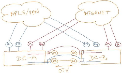
Figure 1: Redundant data centers and their internet connectivity
Layer-2 DCI was used to avoid IP renumbering in VM mobility and disaster recovery scenarios. Occasional live migration between data centers is used during maintenance and hardware upgrades operations.
The document describes a summary of design challenges sent by readers of ipSpace.net blog and discussed in numerous ExpertExpress engagements. It’s based on real-life queries and network designs but does not represent an actual customer network. Complete document is available as downloadable PDF to ipSpace.net subscribers.
Contents |
IP Addressing and Routing
Numerous IPv4 and IPv6 subnets in different security zones are used within the two data centers. Even though the data centers operate in active-active mode, individual applications typically don’t span both two data centers for performance reasons. Every IPv4 and IPv6 subnet thus has a primary and a backup data center.
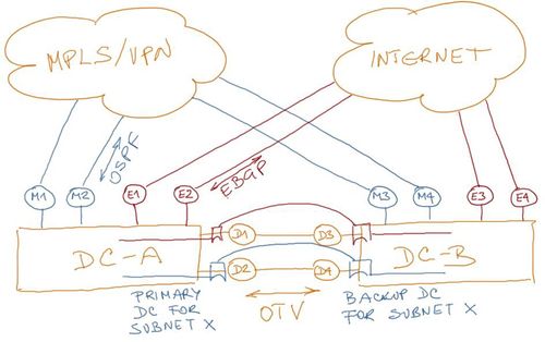
Figure 2: IP addressing and routing with external networks
ACME uses OSPF within its MPLS/VPN network and BGP with upstream Internet Service Providers (ISPs).
Redundancy Removed to Simplify Design Discussions
All critical components of a highly available data center design should be redundant, but it’s sometimes easier to disregard the redundancy of the components not relevant to a particular portion of the overall design to simplify the design discussions.
We’ll assume none of the components or external links are redundant (see Figure 3), but it’s relatively simple to extend a layer-3 design with redundant components.
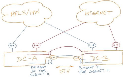
Figure 3: Simplified topology with non-redundant components
Design Requirements
Layer-2 DCI is the least desirable data center interconnect solution[1], as it extends a single broadcast domain (and thus a single failure domain) across multiple sites, turning them into a single availability zone[2].
Furthermore, DCI link failure might result in a split-brain scenario where both sites advertise the same IP subnet, resulting in misrouted (and thus black-holed) traffic[3].
External routing between the two data centers and both Internet and enterprise WAN (MPLS/VPN) network should thus ensure that:
- Every data center subnet remains reachable after a single link or device failure;
- DCI link failure does not result in a split-brain scenario with traffic for the same subnet being sent to both data centers.
- Backup data center (for a particular VLAN/subnet) advertises the subnet after the primary data center failure.
Failure Scenarios
The design described in this document should provide uninterrupted external connectivity under the following conditions:
- Single device or link failure anywhere in the data center network edge;
- Total external connectivity failure in one data center;
- Total DCI link failure;
- Total data center failure.
Stateful devices (firewalls, load balancers) are not included in this design. Each stateful device partitions the data center network in two (or more) independent components. You can apply the mechanisms described in this document to the individual networks; migration of stateful devices following a data center failure is out of scope.
Solution Overview
External data center routing seems to be a simple primary/backup design scenario (see Figure 4):
- Primary data center advertises a subnet with low cost (when using BGP, cost might be AS-path length or multi-exit discriminator attribute);
- Backup data center advertises the same subnet with high cost – even if the DCI link fails, every external router ignores the prefix advertised by the backup data center due to its higher cost.
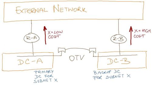
Figure 4: Primary/backup external routing
The primary/backup approach based on routing protocol costs works reasonably well in enterprise WAN network where ACME controls the routing policies, but fails in generic Internet environment, where ACME cannot control routing policies implemented by upstream ISPs, and where every ISP might use its own (sometimes even undocumented) routing policy.
For example, an upstream ISP might strictly prefer prefixes received from its customers over prefixes received from other autonomous systems (peers or upstream ISPs); such an ISP would set local preference on BGP paths received from its customers, making AS path length irrelevant. Routing policy that unconditionally prefers customer prefixes might prevent a straightforward implementation of primary/backup scenario based on routing protocol cost (ex: AS path length).
The only reliable mechanism to implement primary/backup path selection that does not rely on ISP routing policies is conditional route advertisement – BGP routers in backup data center should not advertise prefixes from primary data center unless the primary data center fails or all its WAN connections fail.
To further complicate the design, BGP routers in the backup data center (for a specific subnet) shall not advertise the prefixes currently active in the primary data center when the DCI link fails.
Data center edge routers thus have to employ mechanisms similar to those used by data center switches with a shared control plane (ex: Cisco’s VSS or HP’s IRF): they have to detect split brain scenario by exchanging keepalive messages across the external network. When the backup router (for a particular subnet) cannot reach the primary router through the DCI link but still reaches it across the external network, it must enter isolation state (stop advertising the backup prefix).
You can implement the above requirements using neighbor advertise-map functionality available in Cisco IOS in combination with IP SLA-generated routes (to test external reachability of the other data center), with Embedded Event Manager (EEM) triggers, or with judicious use of parallel IBGP sessions.
Notes
- See Data Center Interconnects webinar for more details
- Layer-2 is a single failure domain
http://blog.ioshints.info/2012/05/layer-2-network-is-single-failure.html - The difference between Metro Ethernet and stretched data center subnets
http://blog.ioshints.info/2012/07/the-difference-between-metro-ethernet.html
Get the complete document
Complete case study, including design and deployment guidelines and sample configuration snippets is available to ipSpace.net subscribers. Select the Case studies tab after logging into the webinar management system.
Case Studies
- BGP Convergence Optimization
- BGP Routing in DMVPN Access Network
- Combine Physical and Virtual Appliances in a Private Cloud
- Designing a Private Cloud Network Infrastructure
- Integrating Internet VPN with MPLS VPN WAN
- Redundant Data Center Internet Connectivity
- Redundant Server-to-Network Connectivity
- Replacing the Central Firewall
- Scale-Out Private Cloud Infrastructure
Webinar roadmaps
- Cloud Computing and Networking
- Containers and Docker
- Data Center Infrastructure
- Internetworking Technologies
- IP version 6
- Network Automation
- Network Security
- Network Virtualization
- Networking Fundamentals
- Software Defined Networking (SDN)
- Software-Defined Data Centers (SDDC)
- Virtual Private Networks