Integrating DMVPN-based Internet VPN with MPLS/VPN WAN
ipSpace.net » Case Studies » Integrating DMVPN-based Internet VPN with MPLS/VPN WAN
A large enterprise (the Customer) has a WAN backbone based on MPLS/VPN service offered by a regional Service Provider (SP). The service provider has deployed Customer Premises Equipment (CPE) routers at remote sites. Customer routers at the central site are connected directly to the SP Provider Edge (PE) routers with 10GE uplinks as shown in Figure 1.
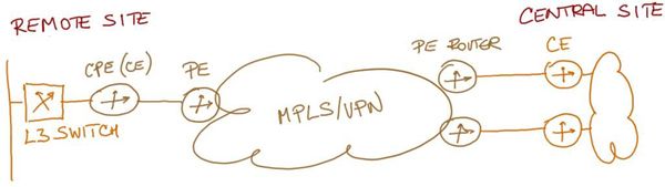
Figure 1: Existing MPLS VPN WAN network topology
The traffic in the Customer’s WAN network has been increasing steadily prompting the customer to increase the MPLS/VPN bandwidth or to deploy an alternate VPN solution. The Customer decided to trial IPsec VPN over the public Internet, initially as a backup, and potentially as the primary WAN connectivity solution.
The customer will deploy new central site routers to support the IPsec VPN service. These routers will terminate the IPsec VPN tunnels and provide whatever other services are needed (example: QoS, routing protocols) to the IPsec VPNs.
New low-end routers connected to the existing layer-3 switches will be deployed at the remote sites to run the IPsec VPN (Figure 2 shows the proposed new network topology).
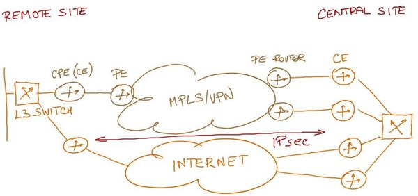
Figure 2: Proposed new network topology
The document describes a summary of design challenges sent by readers of ipSpace.net blog and discussed in numerous ExpertExpress engagements. It’s based on real-life queries and network designs but does not represent an actual customer network. Complete document is available as downloadable PDF to ipSpace.net subscribers.
IP Routing Overview
The customer is using OSPF as the sole routing protocol and would prefer using OSPF in the new IPsec VPN.
OSPF routes are exchanged between Customer’s core routers and SP’s PE routers, and between Customer’s layer-3 switches and SP’s CPE routers at remote sites. Customer’s central site is in OSPF area 0; all remote sites belong to OSPF area 51.
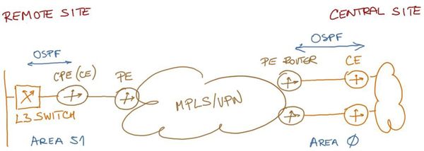
Figure 3: OSPF areas
CPE routers deployed at Customer’s remote sites act as Customer Edge (CE) routers from MPLS/VPN perspective. The Service Provider uses BGP as the routing protocol between its PE- and CE routers, redistributing BGP routes into OSPF at the CPE routers for further propagation into Customer’s remote sites.
OSPF routes received from the customer equipment (central site routers and remote site layer-3 switches) are redistributed into BGP used by the SP’s MPLS/VPN service, as shown in Figure 4.
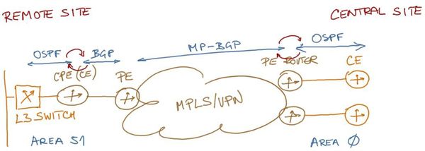
Figure 4: OSPF-to-BGP route redistribution
The CPE routers redistributing remote site OSPF routes into SP’s BGP are not PE routers. The OSPF routes that get redistributed into BGP thus do not have OSPF-specific extended BGP communities, lacking any indication that they came from an OSPF routing process. These routes are therefore redistributed as external OSPF routes into the central site’s OSPF routing process by the SP’s PE routers.
The OSPF routes advertised to the PE routers from the central site get the extended BGP communities when they’re redistributed into MP-BGP, but since the extended VPNv4 BGP communities don’t propagate to CE routers running BGP with the PE routers, the CPE routers don’t receive the extended communities indicating the central site routes originated as OSPF routes. The CPE routers thus redistribute routes received from other Customer’s sites as external OSPF routes into the OSPF protocol running at remote sites.
Summary: All customer routes appear as external OSPF routes at all other customer sites (see Figure 5 for details).
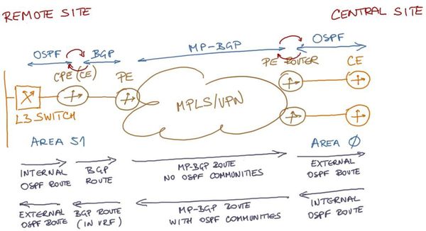
Figure 5: Inter-site OSPF route advertisements
Design Requirements
The VPN-over-Internet solution must satisfy the following requirements:
- Dynamic routing: the solution must support dynamic routing over the new VPN infrastructure to ensure fast failover on MPLS/VPN or Internet VPN failures;
- Flexible primary/backup configuration: Internet VPN will be used as a backup path until it has been thoroughly tested. It might become the primary connectivity option in the future;
- Optimal traffic flow: Traffic to/from sites reachable only over the Internet VPN (due to local MPLS/VPN failures) should not traverse the MPLS/VPN infrastructure. Traffic between an MPLS/VPN-only site and an Internet VPN-only site should traverse the central site;
- Hub-and-spoke or peer-to-peer topology: Internet VPN will be used in a hub-and-spoke topology (hub = central site). The topology will be migrated to a peer-to-peer (any-to-any) overlay network when the Internet VPN becomes the primary WAN connectivity solution.
- Minimal configuration changes: Deployment of Internet VPN connectivity should not require major configuration changes in the existing remote site equipment. Central site routers will probably have to be reconfigured to take advantage of the new infrastructure.
- Minimal disruption: The introduction of Internet VPN connectivity must not disrupt the existing WAN network connectivity.
- Minimal dependence on MPLS/VPN provider: After the Internet VPN infrastructure has been established and integrated with the existing MPLS/VPN infrastructure (which might require configuration changes on the SP-managed CPE routers), the changes in the traffic flow must not require any intervention on the SP-managed CPE routers.
Solution Overview
Internet VPN will be implemented with the DMVPN technology to meet the future requirements of peer-to-peer topology. Each central site router will be a hub router in its own DMVPN subnet (one hub router per DMVPN subnet), with the remote site routers having two DMVPN tunnels (one for each central site hub router) as shown in Figure 6.
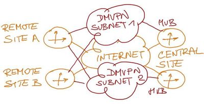
Figure 6: DMVPN topology
The new VPN infrastructure could use OSPF or BGP routing protocol. The Customer would prefer to use OSPF, but the design requirements and the specifics of existing MPLS/VPN WAN infrastructure make OSPF deployment exceedingly complex.
Using BGP as the Internet VPN routing protocol would introduce a new routing protocol in the Customer’s network. While the network designers and operations engineers would have to master a new technology (on top of DMVPN) before production deployment of the Internet VPN, the reduced complexity of BGP-only WAN design more than offsets that investment.
Get the complete document
Complete case study, including design and deployment guidelines and sample configuration snippets is available to ipSpace.net subscribers. Select the Case studies tab after logging into the webinar management system.
Case Studies
- BGP Convergence Optimization
- BGP Routing in DMVPN Access Network
- Combine Physical and Virtual Appliances in a Private Cloud
- Designing a Private Cloud Network Infrastructure
- External Routing with Layer-2 Data Center Interconnect (DCI)
- Redundant Data Center Internet Connectivity
- Redundant Server-to-Network Connectivity
- Replacing the Central Firewall
- Scale-Out Private Cloud Infrastructure
Webinar roadmaps
- Cloud Computing and Networking
- Containers and Docker
- Data Center Infrastructure
- Internetworking Technologies
- IP version 6
- Network Automation
- Network Security
- Network Virtualization
- Networking Fundamentals
- Software Defined Networking (SDN)
- Software-Defined Data Centers (SDDC)
- Virtual Private Networks