Redundant Data Center Internet Connectivity
ipSpace.net » Case Studies » Redundant Data Center Internet Connectivity
A large enterprise (the Customer) has two data centers linked with a fully redundant layer-3 Data Center Interconnect (DCI) using an unspecified transport technology. Each data center has two redundant Internet connections (see Figure 1 for details).
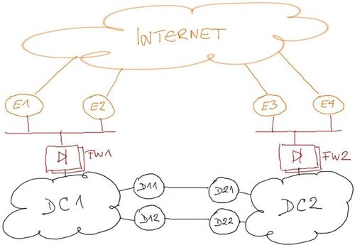
Figure 1: Redundant data centers and their internet connectivity
The customer would like to make the Internet connectivity totally redundant. For example: if both Internet connections from DC1 fail, the public IP prefix of DC1 should remain accessible through Internet connections of DC2 and the DCI link.
The document describes a summary of design challenges sent by readers of ipSpace.net blog and discussed in numerous ExpertExpress engagements. It’s based on real-life queries and network designs but does not represent an actual customer network. Complete document is available as downloadable PDF to ipSpace.net subscribers.
Simplified Topology
All critical components of a redundant data center design should be redundant, but it’s sometimes easier to disregard the redundancy of the components not relevant to a particular portion of the overall design (our scenario: firewalls and DCI routers) to simplify the design discussions (see Figure 2).
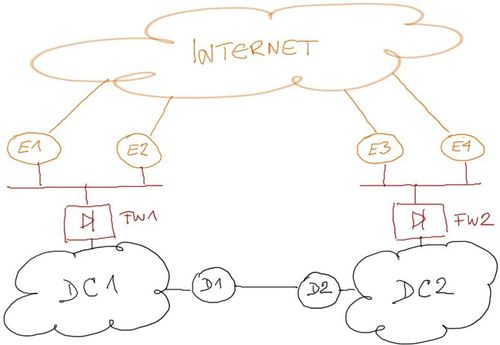
Figure 2: Simplified topology with non-redundant internal components
We’ll further assume that the two sites do not have significant campus networks attached to them. The outbound traffic traversing the Internet links is thus generated solely by the servers (example: web hosting) and not by end-users surfing the Internet.
You can easily adapt the design to a mixed campus/data center design by modeling the campus networks as separate sites attached to the same firewalls or Internet edge LAN.
Design Requirements
A redundant Internet access solution must satisfy the following requirements:
- Resilient inbound traffic flow: both sites must advertise IP prefixes assigned to DC1 and DC2 to the Internet;
- No session loss: Failure of one or more Internet-facing links must not result in application session loss;
- Optimal inbound traffic flow: Traffic for IP addresses in one of the data centers should arrive over uplinks connected to the same data center; DCI link should be used only when absolutely necessary.
- Optimal outbound traffic flow: Outbound traffic must take the shortest path to the Internet; as above, DCI link should be used only when absolutely necessary.
- No blackholing: A single path failure (one or both Internet links on a single site, or one or more DCI links) should not cause traffic blackholing.
Failure Scenarios
This document describes a network that is designed to survive the following failures:
- Single device or link failure anywhere in the network;
- Total Internet connectivity failure in one data center;
- Total DCI link failure;
The design described in this document does not address a total data center failure; you’d need a manual or automatic failover mechanism addressing network, compute and storage components to achieve that goal.
Solution Overview
We can meet all the design requirements by redesigning the Internet Edge layer of the corporate network to resemble a traditional Internet Service Provider design[1].
The Internet Edge layer of the new network should have:
- WAN backbone providing internal connectivity (see Figure 3);
- Edge or peering routers connecting the WAN backbone to Internet peers or upstream providers;
- Edge routers connecting sites to the WAN backbone.
The missing component in the current Internet Edge layer is the WAN backbone. Assuming we have to rely on the existing WAN connectivity between DC1 and DC2, the DCI routers (D11 through D22) have to become part of the Internet Edge layer (outside) WAN backbone as shown in Figure 3.
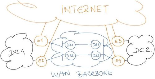
Figure 3: Outside WAN backbone in the redesigned network
The outside WAN backbone can be built with any one of these technologies:
- Point-to-point Ethernet links or stretched VLANs between Internet edge routers. This solution requires layer-2 connectivity between the sites and is thus the least desirable option;
- GRE tunnels between Internet edge routers;
- Virtual device contexts on DCI routers to split them in multiple independent devices (example: Nexus 7000).
- VRFs on the DCI routers to implement another forwarding context for the outside WAN backbone.
Regardless of the technology used to implement the WAN backbone, all the proposed solutions fall in two major categories:
- Layer-2 solutions, where the DCI routers provide layer-2 connectivity between Internet edge routers, either in form of point-to-point links between Internet edge routers or site-to-site VLAN extension.
- Layer-3 solutions, where the DCI routers participate in the WAN backbone IP forwarding.
Notes
- For more details, watch the Redundant Data Center Internet Connectivity video (http://demo.ipspace.net/get/X1%20Redundant%20Data%20Center%20Internet%20Connectivity.mp4)
Get the complete document
Complete case study, including design and deployment guidelines and sample configuration snippets is available to ipSpace.net subscribers. Select the Case studies tab after logging into the webinar management system.
Case Studies
- BGP Convergence Optimization
- BGP Routing in DMVPN Access Network
- Combine Physical and Virtual Appliances in a Private Cloud
- Designing a Private Cloud Network Infrastructure
- External Routing with Layer-2 Data Center Interconnect (DCI)
- Integrating Internet VPN with MPLS VPN WAN
- Redundant Server-to-Network Connectivity
- Replacing the Central Firewall
- Scale-Out Private Cloud Infrastructure
Webinar roadmaps
- Cloud Computing and Networking
- Containers and Docker
- Data Center Infrastructure
- Internetworking Technologies
- IP version 6
- Network Automation
- Network Security
- Network Virtualization
- Networking Fundamentals
- Software Defined Networking (SDN)
- Software-Defined Data Centers (SDDC)
- Virtual Private Networks